
Place of Origin:
Wuhan China
Brand Name:
Springtek
Certification:
ISO9001 RoHS FCC CE
Model Number:
S-Q52AP005-C
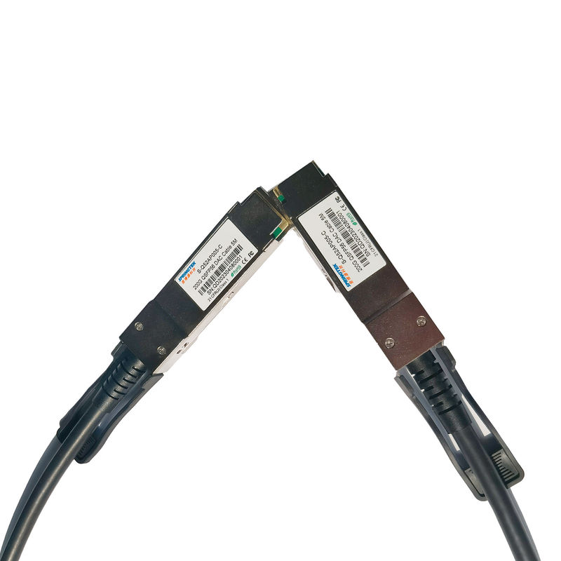
200G QSFP56 to QSFP56 DAC Cable 5M
Ordering information
| Part Number | Product Description | Fiber Spec. |
|
S-Q52AP005-C |
200G QSFP56 DAC Cable 5M |
0~70℃ |
Description
Springtek 200G QSFP5 passive copper cable assembly feature eight differential copper pairs, providing four data transmission channels at speeds up to 56Gbps(PAM4) per channel, and meets 200G Ethernet and InfiniBand requirements. Available in a broad rang of wire gages-from 26AWG through 30AWG-this 200G copper cable assembly features low insertion loss and low cross talk.
Springtek 200G QSFP56 uses PAM4 signals for transmission, which doubles the rate. However, there are more stringent requirements for cable insertion loss. For detailed requirements, Designed for applications in the data center, networking and telecommunications markets that require a high speed, reliable cable assembly, this next generation product shares the same mating interface with QSFP+ form factor, making it backward compatible with existing QSFP ports.
Features
Applications
Recommended Operating Conditions
| Parameter | Symbol | Min | Typical | Max | Unit |
| Storage Ambient Temperature | -40 | +85 | °C | ||
| Operating Case Temperature | Tc | 0 | +70 | °C | |
| Power Supply Voltage | VCC3 | 3.14 | 3.3 | 3.47 | V |
| Relative Humidity (non-condensation) | RS | 35 | 60 | % | |
| Voltage on LVTTL Input | Vilvttl | -0.3 | VCC3 +0.2 | V | |
| Power Supply Current | ICC3 | 15 | mA | ||
| Total Power Consumption | Pd | 0.05 | W | ||
|
Notes: 1.Stress or conditions exceed the above range may cause permanent damage to the device. 2.This is a stress rating only and functional operation of the device at these or any other conditions above those listed in the operational sections of this specification is not applied. 3.Exposure to absolute maximum rating conditions for extended periods may affect device reliability. |
|||||
High Speed Characteristics
| Parameter | Symbol | Min | Typic al | Max | Unit | Note |
| Differential Impedance | RIN,P-P | 90 | 110 | Ώ | ||
| Insertion loss | SDD21 | -16.06 | dB | At 13.28 GHz | ||
|
Differential Return Loss |
SDD11 | See 1 | dB | At 0.05 to 4.1 GHz | ||
| SDD22 | See 2 | dB | At 4.1 to 19 GHz | |||
| Common-mode to common-mode output return loss | SCC11 |
|
-2 |
dB |
At 0.2 to 19 GHz |
|
| SCC22 | ||||||
|
Differential to common-mode return loss |
SCD11 | See 3 |
dB |
At 0.01 to 12.89 GHz | ||
| SCD22 | See 4 | At 12.89 to 19 GHz | ||||
|
Differential to common Mode Conversion Loss |
SCD21 |
-10 |
dB |
At 0.01 to 12.89 GHz | ||
| See 5 | At 12.89 to 15.7 GHz | |||||
| -6.3 | At 15.7 to 19 GHz |
Send your inquiry directly to us