
Place of Origin:
Wuhan China
Brand Name:
Springtek
Certification:
ISO9001 RoHS FCC CE
Model Number:
S-PP2531L10-CD
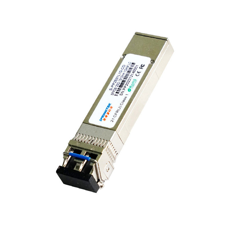
Compatible Cisco LC SFP28 Transceiver , LR fiber optic transceiver module
Ordering information
| Part Number | Product Description |
| S-PP2531L10-CD | SFP28, 25.78Gbps, 1310nm, LC,SMF, 10km , 0ºC~+70ºC, With DDM |
Description
Springtek SFP28 transceiver is designed to transmit and receive optical data over single mode optical fiber for link length 10km.
The SFP28 10km module electrical interface is compliant to SFI electrical specifications. The transmitter input and receiver output impedance is 100 Ohms differential. Data lines are internally AC coupled. The module provides differential termination and reduce differential to common mode conversion for quality signal termination and low EMI.
Features
LC Duplex optical interface
1310nm DFB transmitter, PIN receiver
Applicable for 10km SMF connection
All-metal housing for superior EMI performance
Single 3.3V power supply
1.5W maximum power consumption
Cost effective SFP+ solution, enables higher port
densities and greater bandwidth
Operating case temperature: 0 to +70°C
Compatible with RoHS
Applications
eCPRI&CPRI
Absolute Maximum Ratings
| Parameter | Symbol | Min | Typ | Max | Unit |
| Power Supply Voltage | Vcc | -0.5 | 4 | V | |
| Storage Temperature Range | Ts | -40 | 85 | °C | |
| Relative Humidity - Storage | RHS | 0 | 95 | % | |
| Relative Humidity - Operating | RHO | 0 | 85 | % |
Recommended Operating Conditions
| Parameter | Symbol | Min | Typ | Max | Unit |
| Case Operating Temperature Range | Tc | 0 | +70 | °C | |
| Power Supply Voltage | Vcc | 3.14 | 3.3 | 3.47 | V |
| Supply Current | Icc | 600 | mA | ||
| Data Rate | BR | - | 25.78 | - | Gbps |
Electrical Characteristics
| Transmitter Electrical Characteristics | |||||
| Parameter | Symbol | Min | Typ | Max | Unit |
| Differential Input Voltage Swing | VIN | 200 | - | 900 | mV |
| Tx Differential Input Impendence | ZIN | - | 100 | - | Ω |
| Transmitter Disable Voltage | VDIS | 2.0 | - | VCC+0.3 | V |
| Transmitter Enable Voltage | VEN | 0 | - | 0.8 | V |
| TFAULT Logic High | VTFH | 2.4 | - | VCC | V |
| TFAULT Logic Low | VTFL | VEE | - | VEE+0.4 | V |
| Receiver Electrical Characteristics | |||||
| Parameter | Symbol | Min | Typ | Max | Unit |
| Differential output Voltage Swing | VOUT | 300 | - | 850 | mV |
| Rx Differential Output Impendence | ZOUT | - | 100 | - | Ω |
| LOS Assert Voltage | VLOSA | 2.4 | - | VCC | V |
| LOS De-assert Voltage | VLOSD | VEE | - | VEE+0.4 | V |
Optical and Electrical Characteristics
| Transmitter Electrical Characteristics | ||||||||||
| Parameter | Symbol | Min. | Typ. | Max. | Unit | Note | ||||
| Center Wavelength Range | λ | 1295 | 1310 | 1325 | nm | |||||
| Spectral Width@-20dB | Δλ | - | - | 1 | nm | |||||
| Side Mode Suppression Ratio | SMSR | 30 | - | - | dB | |||||
| Launch Optical Power | Pout | -7 | - | 2 | dBm | 1 | ||||
| Optical Modulation Amplitude | OMA | -4 | - | 2.2 | dBm | |||||
| Launch Power in OMA-TDP | -5 | dB | ||||||||
| Transmitter Dispersion Penalty | TDP | - | - | 2.7 | dB | |||||
| Average launch power of OFF transmitter | -20 | dBm | ||||||||
| Extinction Ratio | ER | 3 | - | - | dB | |||||
| Relative Intensity Noise | RIN | - | - | -130 | dB/Hz | |||||
| Eye Diagram | Complies with IEEE802.3cc eye masks when filtered | |||||||||
| Receiver Electrical Characteristics | ||||||||||
| Parameter | Symbol | Min. | Typ. | Max. | Unit | Note | ||||
| Operating Central Wavelength | λ | 1295 | 1310 | 1325 | nm | |||||
| Unstressed Receiver OMA Sensitivity | Sen | - | - | -12 | dBm | 2 | ||||
| Maximum Receiver Power OMA | - | - | 2.2 | dBm | ||||||
| Receiver Reflectance | RFL | - | - | -26 | dB | |||||
| LOS Assert | LOSA | -30 | - | - | dBm | |||||
| LOS De-Assert | LOSD | - | - | -14 | dBm | |||||
| LOS Hysteresis | LOSH | 0.5 | - | - | dB | |||||
| Note: | ||||||||||
|
1. Average power figures are informative only, per IEEE 802.3cc. 2. Measured with 231-1 PRBS@25.78125Gbps,BER<5E-5 |
||||||||||
Send your inquiry directly to us